|
|
|
Who's Online
There currently are 6043 guests online. |
|
Categories
|
|
Information
|
|
Featured Product
|
|
|
 |
|
|
There are currently no product reviews.
 ;
Nice to have the service manual for the Sony DCR-TRV345E now. The document is of excellent quality.
 ;
MACKIE HR824 26 pages English-only Service Manual contains:
1) HR824 technical overview with the description of front and rear panel switches.
2) HR824 specs
3) Block Diagram
4) Wiring Diagram
5) Packaging management
6) Spare part & final assembly list (for PCB rev A and B) + exploded view
7) Test Procedures (where, how to measure voltage...) including Test Point diagram on the PCB.
8) IC and Transistor charts.
Excellent guide: very clear, good scan quality enabling us to print readable diagram :-)
Note:
Mackie HR824 make extensive use of surface mount devices (SMD). Service on the HR824 must
only be undertaken by experienced service technicians with the right tools, experience and patience to perform surface mount rework when needed.
;
This Service manual is very well scanned and its clean to read, no any anti-theft words that un-english could understand. I got my CCD600 working with this manual and it´s clear shematics :)
;
I was very pleased with the service provided and was surprised at how good the quality was of the manual. I thought it may be a third generation copy or so, but it is as good as the websites that charge 3 times this much. I repair some electronics for family and friends without charge, so this is perfect for me. Thank you very much.
;
The service was great and the document was also great. Highly recommend!!!!
If anyone has a users manual... Please email me. need one. $ [email protected]
ELECTRICAL ADJUSTMENTS
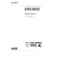
2-7: HORIZONTAL POSITION 1. Receive the monoscope pattern. 2. Using the remote control, set the brightness and contrast to normal position. 3. Activate the adjustment mode display of Fig. 1-1 and press the channel button (08) on the remote control to select "H POSI(50)". 4. Press the VOL. UP/DOWN button on the remote control until the SHIFT quantity of the OVER SCAN on right and left becomes minimum. 5. Receive the monoscope pattern of NTSC. 6. Using the remote control, set the brightness and contrast to normal position. 7. Activate the adjustment mode display of Fig. 1-1 and press the channel button (39) on the remote control to select "H POSI(60)". 8. Press the VOL. UP/DOWN button on the remote control until the SHIFT quantity of the OVER SCAN on right and left becomes minimum. 2-8: VERTICAL SIZE 1. Receive the monoscope pattern. 2. Using the remote control, set the brightness and contrast to normal position. 3. Activate the adjustment mode display of Fig. 1-1 and press the channel button (11) on the remote control to select "V SIZE(50)". 4. Press the VOL. UP/DOWN button on the remote control until the SHIFT quantity of the OVER SCAN on upside and downside becomes 8 ± 3%. 5. Receive the monoscope pattern of NTSC. 6. Using the remote control, set the brightness and contrast to normal position. 7. Activate the adjustment mode display of Fig. 1-1 and press the channel button (12) on the remote control to select "V SIZE(60)". 8. Press the VOL. UP/DOWN button on the remote control until the SHIFT quantity of the OVER SCAN on upside and downside becomes 8 ± 3%. 2-9: BRIGHT CENT 1. Place the set with Aging Test for more than 15 minutes. 2. Receive the monoscope pattern. (RF Input) 3. Using the remote control, set the brightness and contrast to normal position. 4. Activate the adjustment mode display of Fig. 1-1 and press the channel button (17) on the remote control to select "BRIGHT CENT". 5. Press the VOL. UP/DOWN button on the remote control until the white 25% is starting to be visible. 6. Receive the monoscope pattern. (Audio Video Input) 7. Press the AV button on the remote control to set to the AV mode. Then perform the above adjustments 3~5. 2-10: CONT CENT 1. Place the set with Aging Test for more than 15 minutes. 2. Activate the adjustment mode display of Fig. 1-1 and press the channel button (22) on the remote control to 3. select "CONT CENT". 4. Press the VOL. UP/DOWN button on the remote control until the contrast step No. becomes "30". 5. Press the AV button on the remote control to set the AV mode. Then perform the above adjustments 1, 2. D-2 2-11: COLOR CENT 1. Receive the color bar pattern. (RF Input) 2. Connect the oscilloscope to TP023. 3. Using the remote control, set the brightness, contrast and color to normal position. 4. Activate the adjustment mode display of Fig. 1-1 and press the channel button (25) on the remote control to select "COLOR CENT". 5. Adjust the VOLTS RANGE VARIABLE knob of the oscilloscope until the range between white 100% and 0% is set to 5 scales on the screen of the oscilloscope. 6. Press the VOL. UP/DOWN button on the remote control until the red color level is adjusted to 85 ± 10% for the white level. (Refer to Fig. 2-2) 7. Receive the color bar pattern. (Audio Video Input) 8. Press the AV button on the remote control to set the AV mode. Then perform the above adjustments 2~6.
85%
100%
Fig. 2-2 2-12: VCO COASE/VCO FINE 1. Connect the oscillator (39.5MHz) to between the TP003 and the (GND) of TU001. 2. Activate the adjustment mode display of Fig. 1-1 and press the channel button (13) on the remote control to select "VCO COASE". 3. Press the VOL. UP/DOWN button on the remote control until the "+" appear on the screen. 4. Press the CH UP button once to set to "VCO FINE" mode. 5. Press the VOL. UP/DOWN button on the remote control to select the 4 step down point from the upper limit on the "+". (Example: In case of the "+" point 30~41, select 37.) 2-13: VERTICAL POSITION 1. Receive the monoscope pattern. 2. Using the remote control, set the brightness and contrast to normal position. 3. Activate the adjustment mode display of Fig. 1-1 and press the channel button (09) on the remote control to select "V POSI(50)". 4. Check if the step No. V. POSI is "08". 5. Adjust the VR401 until the horizontal line becomes fit to notch of the shadow mask.
|
|
|
> |
|